Apr
Time to Rethink Resharpening Gundrills
- 2018
- Anthony Fettig
By Eric Krueger and Ryan Funk, Engineering Team, UNISIG
Originally posted in Manufacturing News
The modern gundrill is an engineering marvel, a well-designed piece of equipment that does one thing exceptionally well. A new gundrill will produce round, straight holes with enhanced cylindricity even at its deepest points. And it does all this while simultaneously providing a fine I.D. finish and excellent tool life.
 Like all tools, gundrills wear out, typically after drilling around 1,000″. While a talented operator can still drill a hole with a worn gundrill, it will more often result in a loss of hole tolerance and finish at best. As gundrills wear, they require more thrust and torque while producing more run-out and experiencing greater drift. A dull cutting edge will produce irregular chips, which in turn cause spikes in coolant pressure – sure signs that failure is imminent.
Unlike some tools, gundrills are excellent candidates for resharpening. When performed correctly, the same gundrill can be resharpened to perform as well as a new drill as many as 8 to 10 times. The only significant difference between a resharpened gundrill and a freshly produced tool from the OEM is a slight back taper, an issue only for shops that require tolerances far beyond most manufacturers’ needs – all other shops can simply account for the ever-so-slightly reduced tool diameter. Otherwise, the only visible difference will be seen in the length of solid carbide on the gundrill’s tip.
 Even coated drills can be sharpened. Naturally, this will reveal the raw carbide on the face, but this does not impact performance. The coating will remain on the wear pads and continue to improve the gundrill’s size control and ability to leave behind a finished surface. Tool life will be impacted, but the only other option is having it fully resharpened and re-coated by the OEM, which will likely be less cost effective.
Manufacturers have several options for resharpening their gundrills. For specialized gundrills, such as twin-flute tools and those intended for ultra-high-feed applications with chipbreakers below a coating, resharpening is something that only a gundrill’s OEM can do. A local sharpening service will likely have the proper equipment, but this requires having redundant tooling and factoring in lead time and transportation costs.
However, both of these methods result in a loss of process intelligence. The grinding process can offer valuable information manufacturers can use to optimize their gundrilling applications. As a result, more manufacturers that use gundrills are choosing to resharpen their tools in-house.
 The main risk of performing resharpening operations in-house is poorly sharpened gundrills. Without the correct tip geometry, gundrills do everything worse: size control, roundness, cylindricity, finish, chip control, straightness and depth all negatively impact workpiece quality and result in significantly diminished tool life. This will cause operators to reduce feedrates or change out tools more frequently to achieve the necessary tolerances and out of fear of catastrophic tool failure.
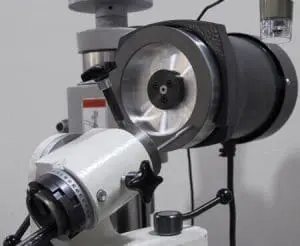
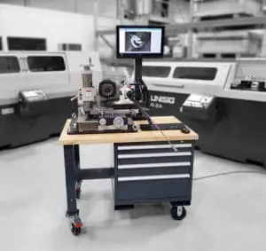
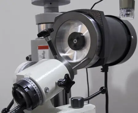
Modern gundrill grinding systems make it easy to avoid these consequences. For the greatest advantage, one needs the full system. That means a grinder, the appropriate gundrill fixture and equipment for calibrating and inspecting the drill tip.
A basic, high-precision manual tool grinder is used as a platform for these systems, though the length of some gundrills necessitates a reinforced table for sufficient accuracy. Choosing a fixture can be more complicated, as gundrills can be ground in two different ways. Sweep grinding leaves behind a gradual transition between elements of the tip’s geometry, while facet grinding creates distinct geometry. UNISIG typically recommends facet grinding, because the slight increase in tip strength produced by a sweep grind is outweighed by the repeatability and greater ease of inspection offered by facet grinds.
The final piece of advanced gundrill grinding systems involves a digital inspection camera capable of viewing and storing magnified images. Ideally, this will allow the user to perform measurements and identify flaws without taking the tool out of the fixture. In addition to allowing for highly precise grinding, this inspection is vital for process optimization.
Process optimization capability is the real added value conferred by performing gundrill resharpening in-house. Frequent inspection allows for the maximization of tool life. Shops become familiar with the wear patterns created by a given application and may find they are replacing gundrills too often. If a gundrill tip has even wear across its entire cutting edge, it could easily have many hundreds of inches of life left, something that will only become apparent with repeated inspections.
In-house gundrill resharpening also ensures that shops can obtain the best tip geometry for their given applications. Whether it is uneven or unexpected wear, or the sudden appearance of chips in the cutting edge, once a shop identifies an irregularity, they can then adjust speeds and feeds to optimize the process. The inspection equipment even makes working with tooling OEMs easier, since shops can send them a measurement set and picture of a tool when asking for advice on how to improve the geometry.
With more experience, it becomes possible to tie a wear condition back to the process. For example, if there is a visible build-up along the cutting edge, it is often because the rotational speed is too slow. Conversely, if the edge is wearing faster than the tooling supplier’s data suggests, the tool is likely spinning too fast. Meanwhile, a chipped cutting edge suggests the feedrate was too high. With this know-how, shops can optimize the process and avoid future problems.
Fortunately, modern gundrill grinding systems make developing this know-how easy to achieve; in fact, the process usually takes longer to describe than it does to perform. After clamping in the gundrill, an operator can use geometry data from the tooling supplier to calibrate the camera. With the latest human-machine interface software, this can be as simple as drawing a line on the screen to establish the known gundrill diameter for repeatability purposes.
After calibration is complete, grinding can begin. The grinding wheel, turning in the direction toward the drill edge, makes contact with the drill tip after the operator confirms the correct rotational and X- and Z-axis orientations. A standard starting point grind will begin with the tip angled at +30° horizontally and +15° vertically with the rotation at +5°. The Y-axis is used to hold the tip to the grinder while feed is performed along the Z-axis at a rate of about 0.002″ per pass.
Some gundrills include an outer secondary angle parallel to the front cutting edge where the primary and secondary angles meet. It is critical that this primary facet is relatively narrow, since too much width will increase heat production and, consequently, reduce tool life. The operator next moves to the inner relief facet by moving the grind fixture -20° vertically in the opposite direction from the primary angle. This movement results in the formation of a point position with a length that is exactly 1/4 of the drill’s diameter, or the “D/4″ position, but other lengths may be necessary depending on the material.
Next, the operator moves to the front clearance, a facet with a point close to – but not touching – the front cutting edge. With standard gundrill tip geometry, a 0° horizontal angle and rotation as well as a +26° vertical angle will provide the correct position. While cutting performance improves the closer this point gets to the cutting edge, optimal edge strength requires placing the point slightly behind the edge. If a tip’s geometry requires an outer secondary angle, the front clearance facet’s point should meet it. Otherwise, the point of the facet is placed between 0.02″ and 0.03” behind the front cutting edge.
The final step on the grinder provides the oil dub-off, a facet with an edge tangential to the flute of the gun drill. Operators position the grind fixture at -30° horizontally, +25° vertically and +65° rotationally. The gundrill tip then feeds into the grinder at a rate that prevents cutting into the front cutting edge. The optimal angle meets the inner relief angle at the corner opposite the gundrill’s outside diameter.
After grinding is complete, the operator can use a hand chamfer to create additional clearance for optimal performance. The finished gundrill is now resharpened and ready for use – a process that takes fewer than 10 minutes. Given the ease of use and the significant process optimization opportunities, it is time to re-think gundrill resharpening.
Reposted with permission.


