Mold shops that recognize the potential of technology and equipment, and prioritize both accuracy and productivity will increase their competitiveness in the marketplace. The key is utilizing machines that are engineered to reduce the time-consuming
01

Mar

Building A Mold In Fewer Setups

Mold shops that recognize the potential of technology and equipment, and prioritize both accuracy and productivity will increase their competitiveness in the marketplace. The key is utilizing machines that are engineered to reduce the time-consuming elements of mold manufacturing, increase mold quality, enhance accuracy and eliminate opportunities for human error.

The mold-building process addresses a challenging combination of machining tolerances, further complicated by tedious workpiece setups that enable the machine to interact with the workpiece more precisely across machining and drilling steps.

Machines designed to handle specific moldmaking challenges—such as increasing throughput by eliminating many of the major time-intensive elements involved in creating a mold—are an optimal solution for mold manufacturers looking to gain an advantage. These machines have features that reduce the need for costly fixtures and extended changeovers, and enable a single setup for several machining processes while allowing operations to be performed on all four sides of a workpiece.

A mold on such a machine can be produced using a roughed-out workpiece that is clamped to the table with modular locating components. The part is milled on four sides and drilled at very high feed rates using high-performance gun drills and BTA tools. With the same setup and fixturing, compound angle machining, intersecting bores, pocketing and complex surface milling can be completed accurately and efficiently. Probing for critical features can then be performed. The mold manufacturer saves days in production time.

A capable machine also will meet the high tolerance demands of complex mold profiles. Features contributing to this include a rigid B-axis table that can handle heavy workpieces as well as high moment capacity. Another essential feature is a headstock carrying milling and drilling spindles that can tilt on an A axis without a loss in rigidity, and allows B-axis rotation at extreme angles and larger than typical travels. All of this leads to the elimination of tedious changeover work, which can save valuable time and effort that can then be applied to using advanced technology and creating better molds.

Machines that combine a range of machining and drilling operations, including high-performance milling and deep-hole drilling, can further increase efficiency. These feature multi-axis positioning and are equipped with capable headstocks with geared transmissions, and 50-taper spindles. A deep-hole drilling headstock capable of conventional gundrilling as well as BTA high-performance drilling will be five-to-seven-times faster than gundrilling alone to further increase productivity and maintain accuracy.

Highly productive machines take advantage of opportunities for automating the machining process as well, and they are extremely accurate in dynamic situations regardless of axis orientation. These machines typically are outfitted with several beneficial options, such as glass scales and direct-feedback angular encoders. They also are able to take advantage of volumetric compensation with a standard contouring control. Furthermore, workpiece probing, laser presetting and large-capacity automatic toolchangers allow unattended operation with greater versatility than previously possible. In addition, process feedback further improves a machine’s capabilities by allowing tooling to be pushed to the limit with the assurance of automatic cycle interruption before something catastrophic occurs.

Summary

The seamless integration of multiple technologies and operations in a single machine can be advantageous. Parametric 3D programming, sophisticated post processing, tool management and on-machine verification are common in more and more shops as the technology becomes affordable. Capable machines are engineered to optimize this technology, and this in turn drastically improves the process that competitive mold manufacturers use to succeed.

mold machining

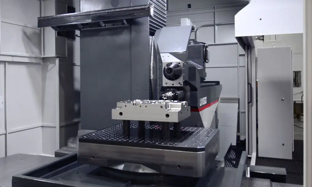
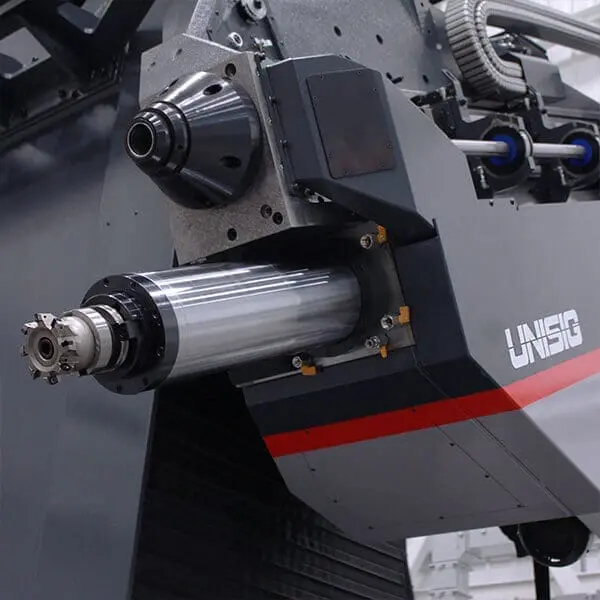
The UNISIG USC-M50 is a capable, durable machining center that combines accurate deep-hole drilling with machining capabilities, enabling moldmakers to perform many necessary machining processes with one setup while maintaining the accuracy required for mold manufacturing.

The USC-M50 machine performs high-speed face milling on a large mold at Concours Mold’s plant in Ontario.

mold manufacturing

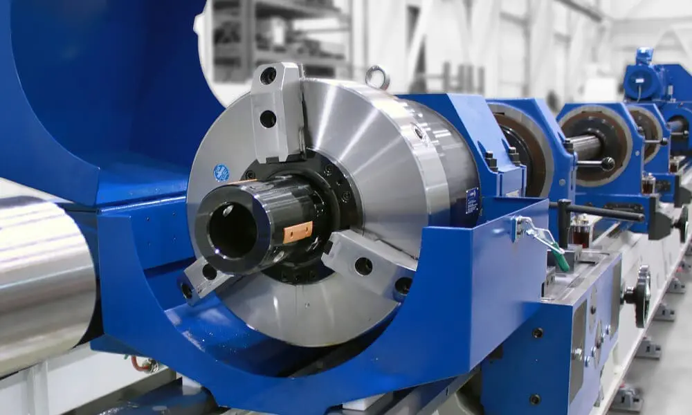
Deep hole drilling is performed on a mold at Concours Mold.

UNISIG's USC-M series for deep hole drilling and machining in mold manufacturing was featured in Canadian Metalworking's piece, "Molding a New Reality"
31

Mar

USC-M Series Featured in Canadian Metalworking

UNISIG’s USC-M series for deep hole drilling and machining in mold manufacturing was featured in Canadian Metalworking’s piece, “Molding a New Reality”. This article highlights noteworthy technology on the forefront of mold machining, and includes UNISIG alongside machine tool builders such as Okuma and Makino. UNISIG’s USC-M machines are highlighted for 7-axis capabilities, and the dramatic advantages of combining processes into a single, capable machine.

UNISIG's USC-M50 mold manufacturing center was proudly featured on the cover of Moldmaking Technology Magazine. The March issue was focused on machining, and the USC-M50 is the ideal machine to feature
01

Mar

USC-M50 Featured on Moldmaking Technology Cover

UNISIG’s USC-M50 mold manufacturing center was proudly featured on the cover of Moldmaking Technology Magazine. The March issue was focused on machining, and the USC-M50 is the ideal machine to feature for this topic, with the revolutionary way it combines machining and deep hole drilling. The headlining article, Building A Mold in Fewer Setups, provided detail about the USC-M50’s capabilities, and the design which reduces setups, removes design restrictions, and improves accuracy and throughput for mold manufacturers.

UNISIG cover Moldmaking Technology
For a hydraulic cylinder to operate effectively, the cylinder’s ID must be precisely round and have a mirror-like surface finish to ensure a tight seal between it and the mating internal piston
27

Sep

Combining Skiving And Burnishing For Cylinder Bores

By Derek Korn, Senior Editor
Originally posted in Modern Machine Shop, August 2012

For a hydraulic cylinder to operate effectively, the cylinder’s ID must be precisely round and have a mirror-like surface finish to ensure a tight seal between it and the mating internal piston. This is commonly achieved through skiving and subsequent roller burnishing inside a tubular workpiece. Skiving uses a set of carbide blades positioned around the diameter of a tool to slice away chips and create a geometrically round bore. Roller burnishing, a cold-working process, uses multiple rollers to compress the peaks of material left behind after skiving to generate an extremely smooth surface finish. Burnishing also introduces a residual stress layer into the cylinder wall, which improves cylinder fatigue life.

These operations are sometimes performed in one pass using a combination skiving/roller burnishing tool on a BTA-style deep-hole drilling machine. However, UNISIG, a supplier of machines, tools and automation for deep hole-making applications, has recently designed machines engineered specifically to perform skiving and roller burnishing operations, noting increasing demand in the hydraulics market for such equipment. Its S-series machines use a single tool for both operations, achieving roundness tolerances of IT-8 or IT-9 and bore surface finishes as smooth as Ra 0.05 to 0.2 micron in one setup and one tool pass.

Sarang Garud, applications engineer for UNISIG, says that 80 percent of the S-series machine design is based on the company’s existing B-series (ballscrew-feed) BTA drilling machines. That said, he notes three distinct features that enable the S-series to be highly effective at skiving and roller burnishing:

Workholding

The tubes used for hydraulic cylinders are relatively thin. Care must be taken to secure the tube rigidly enough for the skiving and roller burnishing processes, but not so tightly as to deform it. Therefore, clamping cones are typically used to hold the tubes on both ends instead of three-jaw chucks. This clamping method also facilitates quick workpiece changeovers in automated environments. In addition, extra support must be provided along the length of the tube due to the inherently high length-to-diameter ratio of these workpieces. The S-series uses a V-shaped hydraulic clamp to provide this support.

Power Train

Thin cuts are taken during skiving. A skiving blade’s radial engagement with the workpiece might be just 2 mm and feeds might be 1 mm per revolution, per blade. However, each tool has two or three skiving blades, which multiples the effective feed rate. Similarly, the cold-working roller burnishing process requires a lot of torque and high spindle speed as it plasticizes and compresses the peaks that skiving leaves behind. As a result, the S-series features a more robust power train with higher horsepower motors and faster spindle speeds than conventional BTA drilling machines.

Rotary Union

A hydraulic circuit inside the skiving and roller burnishing tool expands the skiving blades and burnishing rollers during cutting operations. Therefore, the S-series has a rotary union at one end of the tool headstock to provide a hydraulic connection throughout the length of the rotating tool. Once the cutting pass is completed, the blades and rollers are retracted into the tool as it is removed from the tube. The tool continues to rotate as it is removed, but nylon guides on the tool and continuous coolant delivery prevent damage to the cylinder wall.

The S-series machines are available in skiving/burnishing diameters ranging from 1.5 to 12 inches and lengths to 45 feet (more machines available upon request). The machines can also be modified to perform BTA drilling, counter-boring, and other drilling and tube-finishing operations. In addition, tools can be configured to perform tube finishing on a variety of metals.

skiving machine
skiving and burnishing tool

The S-Series machines are designed to use combination skiving/roller burnishing tools to produce geometrically round holes with quality surface finishes for hydraulic cylinders.

skiving for hydraulic cylinders

Roller burnishing creates a mirror-like surface finish as smooth as Rα 0.05 micron.

Pull boring enables users to achieve remarkable straightness in deep holes. A variation of this technique is also effective when maintaining consistent wall thickness (in long, cast pipes, for example) is top priority.
24

Jun

Pull Boring Highlights the Capability of Deep Hole Making

By Mark Albert, Editor-In-Chief
Originally posted in Modern Machine Shop Online

Pull boring enables users to achieve remarkable straightness in deep holes. A variation of this technique is also effective when maintaining consistent wall thickness (in long, cast pipes, for example) is top priority.

Because the ability to make deep holes effectively and efficiently is critical in many applications, deep hole technology is one of the most highly developed sectors in metalworking. It covers a diverse range of processes and methodologies. UNISIG (Menomonee Falls, Wisconsin), a supplier of machines, tools and automation for deep hole making, says the list of industries it serves includes aerospace, automotive, defense, hydraulics, mold making, oilfield and energy. Yet deep hole making is largely the domain of shops specializing in this capability, whereas technology suppliers such as UNISIG believe that a wider awareness of deep hole making processes would alert new users to valuable opportunities.

As an example of how deep hole technology has mastered some of its most extreme challenges, UNISIG points to one particularly interesting technique: pull boring, which enables users to achieve remarkable straightness in deep holes. A variation of this technique is also effective when maintaining consistent wall thickness (in long, cast pipes, for example) is top priority.

As its name implies, pull boring involves pulling a cutter through an existing hole. Pull boring is usually performed on the same machine that created the original hole. In this case, a boring bar is inserted all the way through the existing hole. After emerging at the opposite end, the bar is fitted with a single-point pull boring head. The bar is then engaged in the tool drive mechanism and drawn back through the workpiece. The bar rotates in one direction, while the workpiece is rotated in the opposite direction by the work spindle. The tooling head holds a carbide insert of the appropriate grade and style for the workpiece material. This insert functions much like an ID turning tool, enlarging the original hole slightly as it is pulled into the workpiece. Coolant pumped around the boring bar channels chips up and out through its hollow center to aid metal removal and protect the surface.

According to Sarang Garud, a UNISIG applications engineer, hole drift tolerances achieved by pull boring can be less than 0.001 inch per foot (0.08 mm/meter) of workpiece length, if material, tooling and process conditions are favorable. However, reaching this level of straightness may require several passes.

For concentricity, a multi-point pull-boring head is used instead of a single-point tool. A multi-point tool typically has between two and six inserts, Mr. Garud says. Wear pads are located in front of the inserts so that the existing ID of the bore provides support during cutting. In contrast, a single-point head is supported by the finished bore ID, so wear pads are located behind the insert.

Mr. Garud notes that pull boring involves several nuances. For example, it is customary to make the original hole by boring halfway through the part, turning it end for end and boring the second half of the hole. This practice reduces the overall out-of-straightness condition in the resulting hole because each half of the bore will show less drift compared to a hole bored all the way through in a single pass. Thus, pull boring has a “head start” in its straightening action.

Pull boring can be applied to any part that a deep hole machine can accommodate. The only limit on part length is the length of the deep hole machine. Likewise, pull boring benefits from the same qualities of accuracy and rigidity in the deep hole machine that affect the original boring operation. In addition, sensing the rate and pressure of coolant flow, which the UNISIG machines do automatically, enables users to protect workpieces and cutting tools by closely monitoring cutting conditions during pull boring.

A special accessory that makes pull boring more efficient is the lantern chuck. A drum-shaped device with openings on opposite sides, the lantern chuck is installed at the workpiece headstock end of the machine. The side openings make it easy to install and align a guide bushing for the pull boring tool. The lantern chuck also eliminates the need to machine a special pilot hole otherwise required so that the pull boring tool enters the workpiece on center.

Advances in deep hole technology will strengthen the capability of specialist shops while widening its use in general metalworking. By providing complete machining systems, tooling, coolant, accessories and process know-how, UNISIG says it is ready to support customers following either trend.

pull boring tool in machine

Although deep hole drilling machines such as this B630 from UNISIG are designed for the special needs of creating holes through long workpieces, they have the flexibility to perform a variety of operations such as boring, counterboring, trepanning, roller burnishing and pull boring.

pull bore operation diagram

Pull boring is a precision operation in which a cutter is pulled through an existing hole to improve straightness.

Related to this article: