Mar
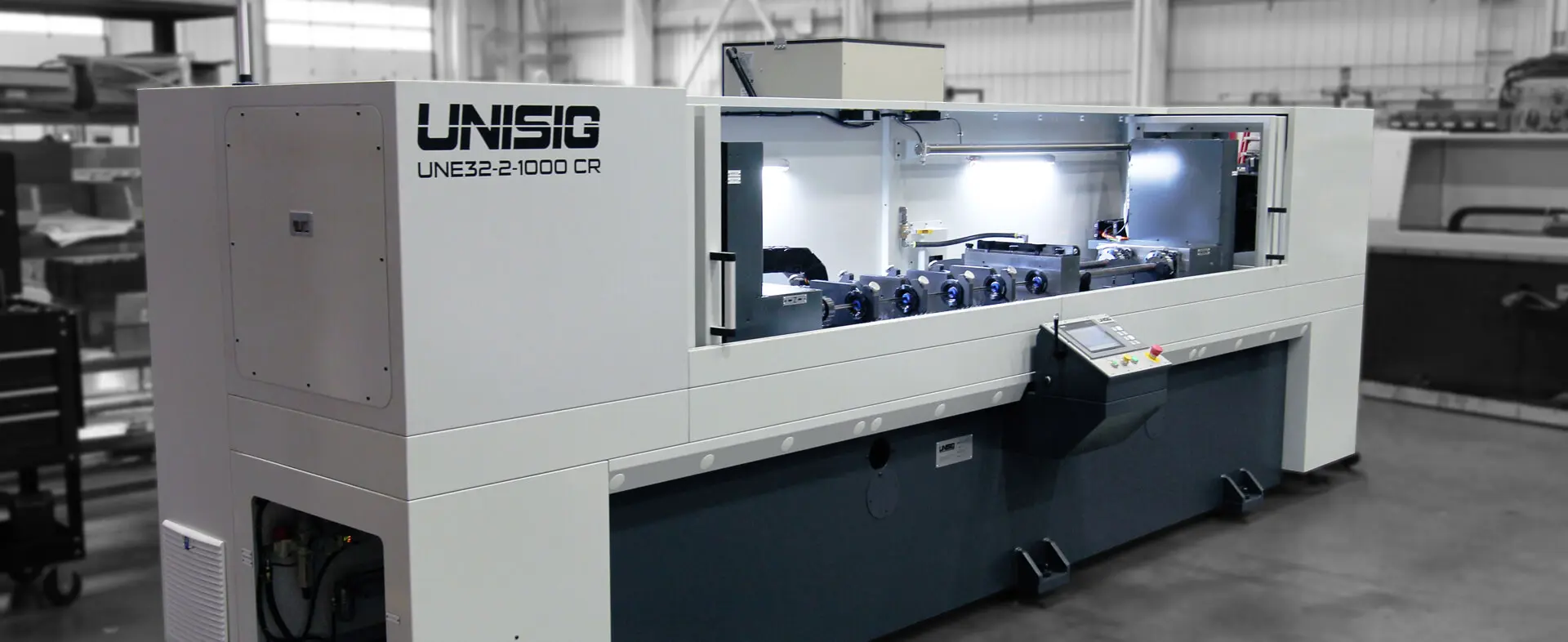
UNISIG LAUNCHES ASSEMBLE-TO-ORDER PROGRAM FOR UNE GUNDRILLING MACHINES
- 2026
- Ampersand Milwaukee

About UNISIG
UNISIG is a leading manufacturer of deep hole drilling machines and automation systems, serving industries ranging from aerospace to medical to moldmaking. Known for engineering innovation and in-house manufacturing capabilities, UNISIG combines precision, performance, and reliability in everything it delivers. For more information, visit www.UNISIG.com
UNISIG maintains inventory of all major UNE platform components and builds each machine to the customer’s specifications after an order is placed. This approach shortens delivery timelines while preserving full machine capability.
Because core components are already stocked and production planning is synchronized through UNISIG’s ERP and manufacturing systems, machine building can begin immediately after configuration is finalized. Lead times are often reduced by up to 50% compared to traditional build-to-order machines.
No. Customers can configure the number of spindles, drill diameter & depth ratings, tooling systems, workholding, automation options, and other application-specific features within the UNE platform. The program balances faster delivery with application flexibility.
Dec
IMPROVING BORE QUALITY WITH SKIVING AND ROLLER BURNISHING
- 2025
- Ampersand Milwaukee

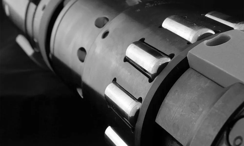
Skiving and roller burnishing is one of the most surprisingly productive ways to achieve high-quality bore finishing in OEM production. Even experienced machinists are impressed when they see raw tubing converted into a mirror-like finish in a single pass at extremely high feed rates. This is achieved by combining two operations into a single tool and having the right machine for the job.
The process works by using a set of floating knives on the front of the tool, followed by rollers. The diameter and finish are adjustable on the head to “dial” in the exact sizes, and the finish can be tuned by adjusting the roller pressure relative to the cutting diameter. Cutting fluid floods the tool to clear chips, and hydraulic actuation protects the finished surface as the tool retracts. The process delivers outstanding accuracy, surface durability, and repeatability across a wide range of bore sizes and production environments.
ACHIEVABLE RESULTS
ACHIEVABLE RESULTS
"Skiving and roller burnishing combines two operations into a single tool."

APPLICATION AND PRODUCTION FLEXIBILITY
UNISIG MACHINES BUILT FOR THE PROCESS
APPLICATION RANGE AND PRODUCTION FLEXIBILITY
UNISIG MACHINES BUILT FOR THE PROCESS
FREQUENTLY ASKED QUESTIONS
Skiving and roller burnishing combine cutting and finishing in a single tool, allowing raw tubing to be converted into a mirror-like finish in one pass. High feed rates, adjustable tool settings, and efficient chip evacuation allow the process to achieve speeds and quality levels that exceed conventional drilling, milling, or turning.
The process supports a wide range of bore diameters from 30 to 500 mm (1.18 to 20 inches) and depths beyond 6 meters (20 feet). UNISIG has applied skiving and roller burnishing to depths exceeding 13 meters (43 feet) in demanding applications.
UNISIG S-Series machines are purpose built for tube production and designed specifically around the skiving and roller burnishing process. B-Series BTA deep hole drilling machines can also integrate this capability, enabling manufacturers to produce both the starting bore and the final high quality finish on one platform.
Nov
ENERGY EFFICIENCY AT UNISIG
- 2025
- Ampersand Milwaukee

Energy efficiency is one area where everyone can agree. It is beneficial for the planet and for profits. A small gundrilling machine may have less than 20 horsepower, while a large BTA drilling machine can exceed 200 horsepower. Regardless of size, every kilowatt-hour of electricity matters. UNISIG designs machines with efficiency in mind because we believe that is how well-planned, modern machines should be built—through thoughtful engineering and design choices that reduce energy consumption and improve performance.
DESIGNING FOR MECHANICAL EFFICIENCY
DESIGNING FOR MECHANICAL EFFICIENCY
"Mechanically efficient designs run cooler, hold tighter tolerances, and last longer."

SMART SYSTEMS THAT CONSERVE ENERGY
COMMITMENT BUILT INTO EVERY MACHINE
SMART SYSTEMS THAT CONSERVE ENERGY
COMMITMENT BUILT INTO EVERY MACHINE
FREQUENTLY ASKED QUESTIONS
Because efficiency impacts both performance and sustainability. Well-designed, efficient machines reduce waste, lower operating costs, and improve reliability.
They recover kinetic energy and, in many cases, return high-quality power to the grid.
Yes, positively. Efficient designs reduce heat, maintain precision, and extend component life, leading to improved accuracy and uptime.
Nov
WHEN IS TREPANNING THE RIGHT CHOICE?
- 2025
- Ampersand Milwaukee

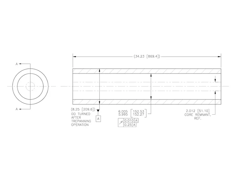
Trepanning is a process that creates a hole in a workpiece by machining only the outer area of the hole, leaving an unmachined core in the center. In contrast, a BTA drill creates the same hole by turning all of the material into chips, leaving no core behind. This provides manufacturers with two distinct ways to create a hole from solid material.
BTA drilling is simple in concept: set up the machine, drill the hole, remove the workpiece, and empty the chip hopper when it’s full. Many manufacturers choose this process for its straightforward operation and the convenience of chip recycling. Trepanning isn’t necessarily more difficult, but it requires more operator involvement. When the hole is complete, the retained core must be removed from the tool between cycles.
Trepanning and BTA solid drilling share the same coolant delivery and chip evacuation systems. Coolant is introduced around the outside of the tool, and chips are exhausted through the drill tube. In BTA drilling, coolant passes freely through the tube, carrying chips to the conveyor. In trepanning, however, chips taken by the coolant must pass by the workpiece core inside the tube. The bore quality between the two methods can be similar, but it depends on the tool design. Trepanning tools with a sufficient cutting width to engage guide pads can achieve diameter tolerances similar to solid drilling. Tools designed for the narrowest width of cut (leaving the largest core) generally produce lower bore quality. For very deep holes, a counter-rotating tool and workpiece are often used. Because the trepanning core rotates with the workpiece, it can create challenges related to vibration or unexpected loading. Once these differences are understood, the key question becomes: When is trepanning the right choice?
ADVANTAGES OF TREPANNING

ADVANTAGES OF TREPANNING
“Trepanning is not just an alternative to BTA drilling—it’s a strategic choice when core recovery, power efficiency, or tooling economy align with production goals.”

LIMITATIONS AND CONSIDERATIONS
EQUIPMENT FOR TREPANNING
LIMITATIONS AND CONSIDERATIONS
EQUIPMENT FOR TREPANNING
FREQUENTLY ASKED QUESTIONS
Trepanning is ideal when core recovery or reduced tooling cost is valuable, or when material properties must be preserved for testing or reuse.
It’s possible, but challenging. Specialized core-breaking or cropping tools are required to separate the core, which adds time and complexity.
Machines must be powerful, and designed for core handling. UNISIG B-Series machines can perform both trepanning and BTA drilling, offering flexibility for different applications.
Nov

PAINT BOOTH INVESTMENT: PRECISION PAINTING FOR UNISIG MACHINES
- 2025
- Ampersand Milwaukee

UNISIG machines are designed to run for 20 years or more in production. While operating, the machines are exposed to factory conditions that are not ideal for precision machinery. Cutting fluid—whether straight oil or water-soluble—contains extreme pressure (EP) additives that improve tool performance but can degrade or damage seals and paint on the machines over time. We want our machines to look good while they age. Part of our strategy for this is to use a two-component polyurethane enamel to paint our base castings, structural frames, machine enclosures, or any fabricated metal parts in our machines. Recently, we targeted our painting department for investment to keep up with our growing company and expanding product line. Our goals for investment were clear:
- Improve the shop environment in the painting area
- Improve the quality of the finished product
- Increase the dimension of parts we could paint
- Reduce the amount of paint used and wasted
- Increase the productivity in painting
- Increase the throughput in the paint department
Manufacturing engineers researched the technology available, and as in most cases in manufacturing, we were even more excited about the project after learning what was possible.
DIMENSIONS AND INTERIOR
“It’s an investment in long-term quality, efficiency, and the appearance of every UNISIG machine that leaves our facility.”
DIMENSIONS AND INTERIOR
“It’s an investment in long-term quality, efficiency, and the appearance of every UNISIG machine that leaves our facility.”

AIR HANDLING AND PAINT MIXING
TRAINING, MAINTENANCE, AND CONTINUOUS IMPROVEMENT
AIR HANDLING AND PAINT MIXING
TRAINING, MAINTENANCE, AND CONTINUOUS IMPROVEMENT
FREQUENTLY ASKED QUESTIONS
UNISIG machines are built to perform for decades in production environments, often exposed to cutting fluids and other challenging factory conditions. The investment into advanced paint technology helps protect critical components, maintain a professional appearance, and ensure long-term durability.
The upgraded booth allows UNISIG to paint larger machine components with greater precision and efficiency. It features improved lighting, controlled air handling, and a crane access system for handling large parts—resulting in higher quality finishes and increased throughput.
The automatic mixing system precisely controls the two components of the polyurethane enamel at the spray gun. This ensures a perfect mix every time, reduces paint waste, and gives painters better control over color selection and solvent use—all contributing to consistent, high-quality finishes.